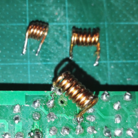
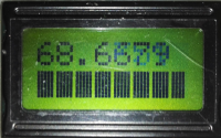
OH8GAD


70 MHz (4 metre) FM transceiver

70 MHz, a.k.a 4 metres, sounds like a good band to play with. It is close to HF, so that construction techniques can be on the simple side, but also high enough so that you don't need huge aerials - a half-wave dipole will only be about 2 metres across.

One thing to note, though. The 70 MHz band is not available in all countries. 70 MHz was freed up when countries closed down their VHF (Band I (VHF low) 54–88 MHz) TV networks. Finland was one of them. However, even in countries that permit operation in this band, there can be differences.

Finnish allocation is from 70.0 MHz to 70.3 MHz.

Frequency Use Notes
70.000 - 70.050 MHz CW, MGM* and propagation beacons Maximum transmission bandwidth of 1 kHz is permitted.
70.050 - 70.175 MHz Narrowband Modes (CW/SSB/MGM) Narrowband modes with a maximum bandwidth of 2.7 kHz: CW,SSB and MGM.
70.175 - 70.225 MHz AMATEUR RADIO TRAFFIC NOT PERMITTED
70.225 - 70.250 MHz Narrowband Modes (CW/SSB/MGM) Narrowband modes with a maximum bandwidth of 2.7 kHz: CW,SSB and MGM.
70.250 - 70.300 MHz FM Channelised Operations & 12.5 kHz spacing
Main calling frequency 70.275 MHz.

* MGM : Machine generated morse.

Source: Michael Fletcher OH2UAE


Because my work space, skills and tools available are pretty limited, I am going to use cheap kits as much as possible. Most of the kits I buy, for the same price, you could hardly buy a few resistors from local shops. The plan is to start with a small kit, modify it, add to it and so on. Grow it, evole it and learn about what you're doing. So, here goes...

The plan:

I bought three FM "70 MHz" wireless microphone kits. I bought three, so that I would build the first "as is", to give a base point to work from, which I'll use as a reference signal source, set to 70.450 MHz, the FM calling channel. Then, the second one, I will build with mods and add-ons straight away. the third kit will, hopefully, become the receiver. In the end, it will become a proper 70 MHz transceiver.

For this project I used the Eqkit RF-01 Wireless Microphone. To measure the frequency, I have the Gooit GY560 Frequency counter. Both were bought from the Banggod website, but as of this update (05/01/2023), neither seem to be available from there. Both can easily be found with a web-search and still bout very cheaply.The kit cost a couple of Euros and the frequency counter cost about EUR 15.00.

.

Gooit GY560 Frequency counter

The Gooit GY560 Frequency counter is specified to cover from 50 MHz to 2.4 GHz, but it will still measure down to about 10 MHz.
I have checked it against a couple of amateur radio transmitters and it measures spot-on in the 2-metre and 70-centimetre bands, so I believe it is OK for purpose.
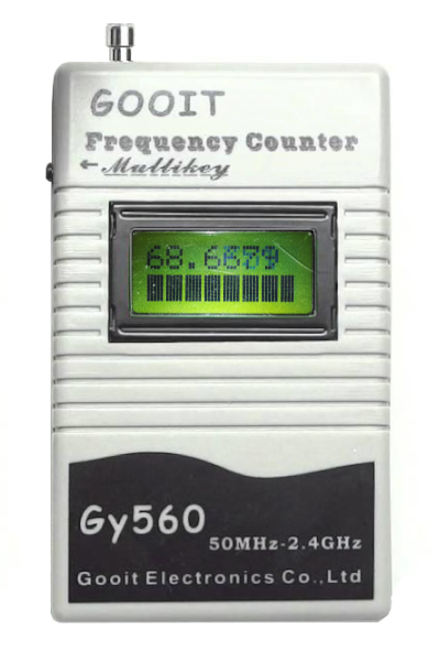
Gooit GY560 Frequency counter

The circuit is a simple FM transmitter with a Hartly LC oscillator circuit:
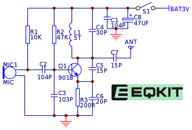
circuit diagram for 70 MHz FM wireless microphone

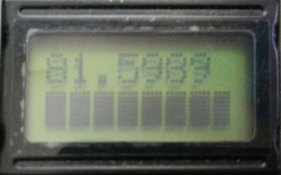
I built the first FM "70 MHz" wireless microphone kit. The information provided states that the default frequency is about 70 MHz. I used the GY560 Frequency Counter to check this, and... It's actually just above 80 MHz. I have actually build a couple of these in the past and in all cases, they are just over 80 MHz. The 4 metre radio amateur band is from 70.0 to 70.5 MHz. So, we're way off to start with.

70 MHz FM wireless microphone Inital frequency

The instructions suggest that you can change the frequency by stretching the coil, but when you make a coil longer, you lower the inductance, so the resonant frequency increases.

I did a little test by pushing my thumb nail between the turns of the coil to stretch it a little bit. You can see that the resonant frequency increases:

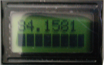
Stretched coil Frequency shift

If you are making this as a "wireless microphone" and want to receive it on a regular Band II (88 to 108 MHz) FM radio, then you should increase the length of the coil until you can recieve the signal on your radio.

In this case, however, we need to lower the frequency. So, we need to either increase the inductance or the capacitance. To increase the inductance, we would need to add more turns. This isn't practicaly possible for this kit - unless you can find a suitable bit of copper wire. The other way is to increase the capacitance value.

To make things easier, I found an online inductance/capacitance/frequency converter (See link below). I put in the values I knew:
Capacitance = 30 pF
Resonant Frequency = 81.5989 MHz

That gave me the value of the inductor as 126.809094104 nH.
I then put that value in the L box and the frequency I want, 70.450 MHz, into the f box, which then gave me the value of capacitor I need:
40.246476833 pF

The nearest value of fixed capacitor to 40.246... pF is 39 pF. Which would give a frequency of about 71.5 MHz, which is too high. I could also put several capacitors in parallel, to make the desired value. For example, 30 + 8,2 + 1 + 1 pF, would eaqual 40.2 pF, which would result in a frequency of 70.49 MHz. Which is about 10 kHz, almost one channel - the 70 MHz band uses 12.5 kHz channel spacing in that part of the band. Also, the inductor is still unreliable, as it can move and change the frequency.

I think the best bet is to put some glue on the coil, to make it more rigid and then fit a variable capacitor, something like 10 - 50 pF. One other thing to note, is that because the board is tiny, any additional components will need to be attached to the board with wires. At these frequencies, even short wires act as inductors, so a variable capacitor would help ensure these extra inductors can be compensated for.

I ordered a 4 to 27 pF trimmer capacitor from my friendly local neighbourhood electronics shop, but while it was in-transit, I found in my collection, a 2 to 20 pF trimmer.

I soldered the trimmer capacitor across C4 (30 pF) on the underside of the PCB - it was a surface-mount device, so I was able to solder the trimmer's tabs directly to the same pads that C4 was soldered to.

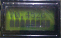
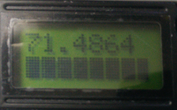
The result was on the new frequency was just over 71 MHz. I then played around, turing the capacitor and found the circuit now tuned from just over 71 MHz to just under 80 MHz. Our goal is 70.450 MHz."

Trimmer capacitor on underside of PCB Frequency shift with extra capacitor

One other change I have made so far, was to remove the small ON/OFF push switch. It is quite fiddly to use and also, touching the baord can cause small shifts in frequency. I replaced the original switch with normal toggle switch, attached to the board with a couple of wires. I can now turn it on and off without touching the PCB.

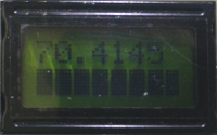
I swapped the 2-20 pF trimmer for a 4 to 27 pF one. The initial frequency was just over 66 MHz. It was quite difficult to get the frequency close to the desired 70.450 MHz, as the slightest touch to the trimmer would send it several hundred kHz in one direction or the other. I finally got it fairly close, at 70.4526 MHz.

4 to 27 pF trimmer Frequency in band

Because both the coil and the trimmer capacitor are mechanical components and very small, they are affected by the slightest movement. Even using a metal screwdriver to adjust the trimmer meant I could not see the true frequency until I removed the blade. The result is that the frequency can drift around.

Frequency drift

After playing experimenting with the capacitors, I then removed the trimmer and had a look at what changing the inductor would do.Naturally, increasing the inductance lowers the frequency. To increase the inductance, more turns of the coil are needed.

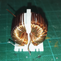
The wire I used was enamelled copper wire from a coil from an old power-supply unit.It was a thicker guage than the original, but this should not have a significant affect on the value of the inductance.I used some drill bits to determine the diameter of the coil. A 4 mm was a bit too tight and a 3 mm was a little loose. I used the 3 mm drill bit, as I expected the coil to unwind a little bit after winding.

toroid from old PSU coils

The original coil has 5-turns. The first one I wound had 6. It gave a frequency of about 84 MHz. I next tried an 8-turn coil, which returned a frequency of about 78 MHz - out of interest, I pushed the 3 mm drill bit into the coil. The measured frequency jumped to just over 132 MHz. A 10-turn coil gave a measured frequency of 68.668 MHz.

10-turn coil 68 MHz

To be continued ...